Series: Closed-Loop Systems | Difficulty: Intermediate | Estimated Time: 2 Hours (Active Build) + Testing
Introduction
In an industrial chemical plant, venting hot gas or dumping hot liquid is considered a catastrophic loss of chemical potential. Engineers use heat exchangers to capture that thermal energy and cycle it back into the system to pre-heat incoming materials.
In a standard household, taking a hot shower is essentially an open-loop energy hemorrhage. You pay to heat water to $105^\circ\text{F}$ ($40^\circ\text{C}$), it touches your body for a fraction of a second, and then vanishes down the drain while it is still $95^\circ\text{F}$ ($35^\circ\text{C}$).
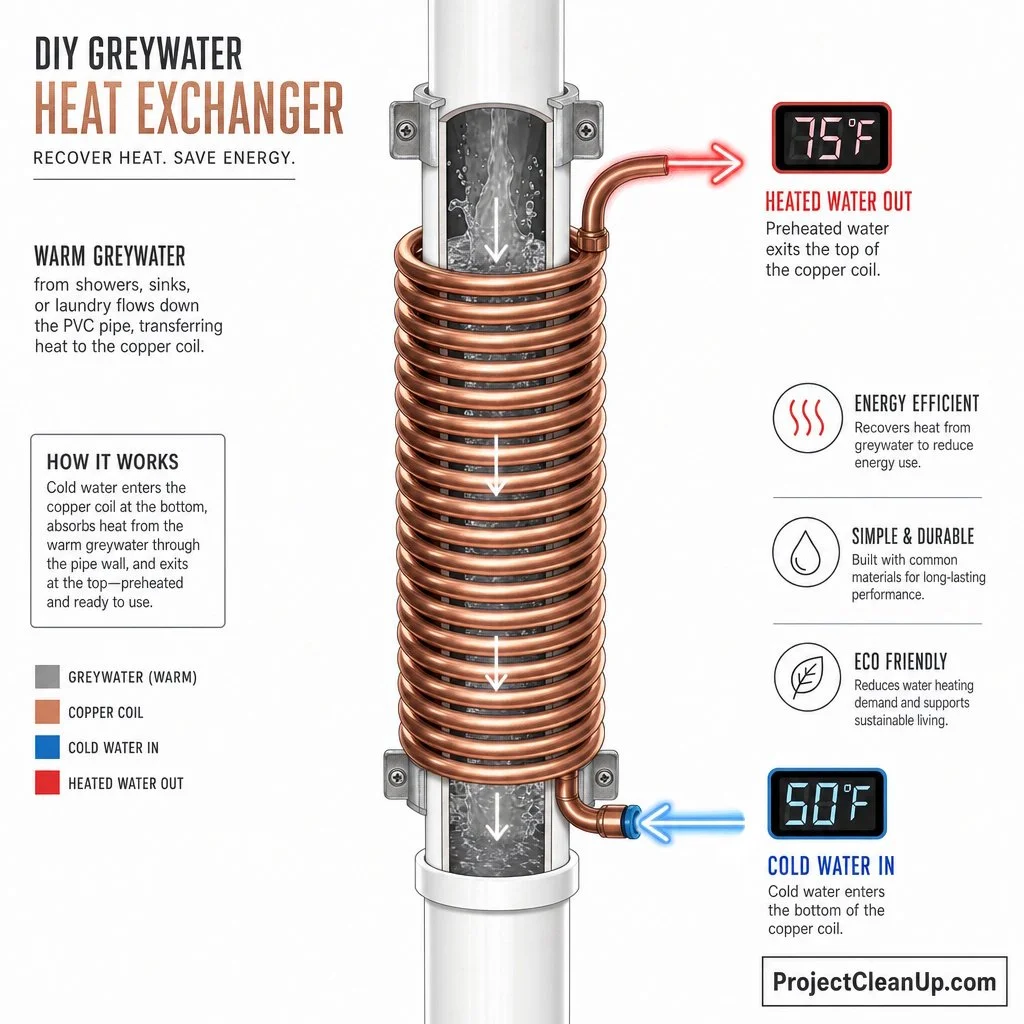
In this module, we are going to build a micro-scale Drain Water Heat Recovery (DWHR) system. By wrapping a high-conductivity copper coil around a section of drain pipe, we will scavenge the escaping thermal energy and use it to passively pre-heat incoming cold water. It requires no electricity, has no moving parts, and relies entirely on the laws of thermodynamics.
The Physics - Counter-Flow Heat Exchange
The core mechanism of this closed-loop system is the First Law of Thermodynamics (energy cannot be created or destroyed, only transferred) combined with Fourier's Law of Thermal Conduction.
When the hot greywater falls down the vertical drain, surface tension causes it to cling to the inside walls of the pipe as a thin, falling film. This maximizes the surface area of the hot water in contact with the pipe wall.
We wrap a copper tube tightly around the outside of this pipe. Copper is an exceptional thermal conductor. The heat moves from the falling water, through the pipe wall, and into the copper coil.
The Counter-Flow Principle:
The direction of the water matters immensely. The hot waste water falls down. We pump the fresh cold water up through the copper coil.
As the cold water enters the bottom of the coil, it meets the coolest part of the falling waste water.
As the fresh water travels up, it gets warmer, but it is continually exposed to even hotter waste water coming from the top.
This "counter-flow" geometry ensures that a temperature gradient is maintained along the entire length of the exchanger, allowing for maximum energy transfer. If they flowed in the same direction, they would simply equalize in the middle.
Safety Framework: R.A.M.P.
Recognize hazards: We are working with plumbing, water pressure, and metal tubing.
Assess risks: Flooding or leaks if connections are loose. Bending copper tubing too sharply can cause it to kink or snap, creating sharp edges.
Minimize risks: Do not cut into your actual home plumbing main lines for this experiment. We are building a "benchtop" simulation model that operates over a sink or bathtub to visualize the physics safely.
Prepare for emergencies: Have a mop and bucket ready. Only use low-pressure pumps (like small aquarium pumps) rather than tapping into high-pressure municipal water lines.
Materials & Equipment
The Hardware:
The Heat Conductor: $10\text{ feet}$ ($3\text{ meters}$) of $\frac{1}{4}\text{-inch}$ flexible soft copper refrigeration tubing.
The Drain Simulation: A $2\text{-foot}$ section of $2\text{-inch}$ diameter PVC pipe (acting as the drain).
Thermal Paste: Standard CPU thermal compound (optional, but highly increases efficiency by bridging microscopic air gaps between the PVC and copper).
Zip Ties or Hose Clamps: To secure the coil.
Tubing: Flexible silicone or vinyl tubing to match the ends of your copper coil.
The Pumps: 2 small submersible aquarium water pumps.
Thermometers: 2 digital meat thermometers or laser temperature guns.
Buckets: Two $5\text{-gallon}$ buckets.
The Procedure: Building the Scavenger
Phase 1: Winding the Coil
The Interface: (Optional) Smear a thin layer of thermal paste along the outside of the $2\text{-foot}$ PVC pipe.
The Wrap: Starting about 3 inches from the bottom of the PVC pipe, begin tightly wrapping the soft copper tubing around the PVC. The coils must be touching each other with zero gaps. Wrap it as tightly as physically possible—air is an insulator, so tight physical contact is mandatory for conduction.
Secure the Ends: Once you reach the top, use heavy zip ties or metal hose clamps to lock the top and bottom of the copper coil in place so it cannot unwind. Gently bend the extreme ends of the copper tubing outward so you can attach your silicone hoses.
Phase 2: The Benchtop Rig
Mounting: Stand the PVC pipe vertically in your bathtub or a large basin.
The Cold Water Source: Fill one $5\text{-gallon}$ bucket with cold tap water (add ice if you want a stark contrast). Drop Pump A into this bucket. Connect Pump A's output hose to the BOTTOM of the copper coil.
The Hot Water Source: Fill the second bucket with hot water (around $105^\circ\text{F} / 40^\circ\text{C}$). Drop Pump B into this bucket. Connect Pump B's output hose so it pours directly down the TOP/INSIDE of the PVC pipe.
Phase 3: Activating the Loop
Baseline Readings: Measure and record the exact temperature of the cold bucket and the hot bucket.
The Cold Flow: Turn on Pump A (the cold water). Water will push up through the copper coil and exit the top. Let it run for 30 seconds to purge air. Measure the temperature of the water exiting the top of the copper coil. It should match the cold bucket.
Engage the Heat Exchanger: Turn on Pump B. Hot water will cascade down the inside of the PVC pipe.
The Data: Wait 60 seconds for the thermal transfer to stabilize. Now, measure the temperature of the clean water exiting the top of the copper coil again.
Observation: You will witness a massive temperature spike. The clean water entering the coil at $50^\circ\text{F}$ might exit at $70^\circ\text{F}$ or $80^\circ\text{F}$, entirely heated by the "waste" water falling past it.
If this were hooked up to your water heater, that $30^\circ\text{F}$ jump represents energy your water heater no longer has to expend. You have scavenged thermal energy that was destined for the sewer.
The Digital Twin: AI Simulation Prompt
Want to see how changing the water speed affects the heat transfer? Copy and paste this prompt into your AI assistant to generate an interactive calculator based on the thermodynamics of heat exchangers.
Prompt to copy/paste:
"I just built a DIY drain water heat exchanger using a copper coil wrapped around a PVC pipe. Please generate an interactive HTML/JS simulation using native canvas or basic DOM elements that models the temperature profile of a Counter-Flow Heat Exchanger.
Include two sliders: 'Hot Water Drain Flow Rate' and 'Cold Water Supply Flow Rate'.
Create a simple 2D line chart showing the length of the pipe on the X-axis and Temperature on the Y-axis.
Draw two lines: a red line representing the hot water dropping in temperature as it falls, and a blue line representing the cold water rising in temperature as it flows upward.
As I adjust the flow rate sliders, the slopes of the temperature lines should dynamically change to reflect standard heat transfer efficiency equations."